Time for a technical deep dive – As you may or may not know, HP 3PAR boasts a sexy array-based software feature set. You’ve probably heard me rave on about it in other posts and podcasts I have done. I’ve worn this fan-boy cap for a while now and spoken about our leading thin suite.
Some 3PAR software features perhaps don’t get as much limelight as our thinning capability or wide striping but they are extremely supportive and tell a great benefit story, especially in the area of High Availability (HA) or Business Continuity (BC). These features are array based and are called peer persistence, peer motion, persistent ports and persistent cache.
The names appear similar but they mean different solutions so let’s take a look at some of these concepts and how they work particularly with the vSphere platform—starting with peer persistence.
Spotlight on HP 3PAR Peer Persistence
Another way to look at peer persistence is to tie it back to something that has been around for a while in the virtual world – VMware vMotion technology.
So what vMotion does for local site workloads, peer persistence does for geographically disparate data centres, meaning it offers transparent site switchover without the application knowing it has happened. It provides a HA configuration between these sites in a metro-cluster configuration.
Peer persistence allows you to extend this coverage across two sites, enabling use of your environment and load balancing your virtual machines (VMs) across disparate arrays. Truly a new way to think of a federated data center in this context IMO. Note, this implies an active\active configuration at the array level but not at the volume level, which is active\passive which infers hosts paths to the primary volume and secondary volume
Transparent switchover and Zero RPO/RTO
What does it mean to offer “transparent site failover”? In the context of 3PAR peer persistence, it simply means that workloads residing in a VMware cluster can shift from site 1 to site 2 without downtime. This makes aggressive RPO\RTOs an achievable reality.
This is particular fit for mission-critical applications or services that may have this RTO/RPO of 0.
Note: I mention VMware for this as this particular technology only currently supports VMware hosts (vSphere 5.0+) and not vMSC.
How does it do it?
Peer persistence leverages HP 3PAR remote copy synchronous to manage the transfer of the remote from local site to remote site and gain acknowledgement back to the host operating system (vSphere in this instance). Today the switchover is a manual process executed via the 3PAR CLI (the automated process is coming later this year).
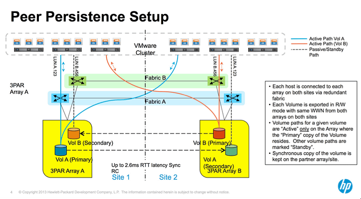
Working with VMware vSphere, this allows your ESXi cluster to virtually span across data centers. So in the above figure VMs are being serviced by HP StoreServ Storage A and other VMs are being serviced by HP StoreServ Storage B but all are existing in the same VMware data center. Moving VMs between sites would typically need a reset, but peer persistence removes this limitation by continuous copying or shadowing the VM on the remote volume via RC and switching over the volumes logically.
I’ll write the high level process with the above figure 1 in mind without any pretty pictures:
- Host can logically see both HP StoreServ Storage arrays by means of stretch fabric.
- VM resides in Site 1, on Volume A. Volume A’s partner (Volume B) is being presented to Host B in Site 2 and can be considered active but not primary.
- The primary and secondary volumes are exported using different Target Port Groups supported by persona 11 (VMware).
This presentation is possible via Asymmetric Logical Unit Access or ALUA allowing a SCSI device (Volume A in this instance) to be masked with same traits (Source WWN).
Provided this configuration exists, the process is:
- Controlled switchover is initiated by user manually via CLI on primary array. Using ‘setrcopygroup switchover <groupname>’
- IO from the host to the primary array is blocked and in flight IO is allowed to drain.
- The remote copy group is stopped and snapshots are taken on the primary array.
- The primary array target port group is changed to transition state.
- The primary array sends a remote failover request to the secondary array.
- The secondary array target port group is changed to transition state.
- The secondary array takes a recovery point snapshot.
- The secondary array remote copy group changes state to become primary-reversed (pri-rev). At this point the secondary volume will become read/write.
- The secondary target port group is changed to active state.
- The secondary array returns a failover complete message to the primary array.
- From here, The primary array target port group is changed to standby state and any blocked IO is returned to the host with the following sense error: “NOT READY, LOGICAL UNIT NOT ACCESSIBLE, TARGET PORT IN STANDBY STATE”
- The host will perform SCSI inquiry requests to detect what target port groups have changed and which paths are now active. Getting your host multipathing configuration is very important here!
- Volume B is now marked primary and hosts continues to access the volume via the same WWN as before. Host IO will now be serviced on the active path to the secondary array without the host application even knowing what happened!
What you need
Here’s your list:
- A WAN link between your two data centers should not have more than 2.6ms latency. This is important as remote copy synchronous needs to be able to send the write and wait for an acknowledgement within a given time frame.
- One thing to note is that previously, vMotion used to be supported only on networks with round-trip (RTT) time latencies of up to 5 ms but with VMware vSphere 5 introduced a new latency-aware Metro vMotion feature that increases the round-trip latency limit for vMotion networks from 5 ms to 10ms. The requirement for 5ms seems to be a thing of the past moving forward allowance cool things like spanned virtual data centres in this regard.
- The ESXi hosts must be configured using 3PAR host Persona 11.
- Host timeouts need to be less than 30 seconds. This time does not include the subsequent recover and reverse operations so leave some headroom.
- The WWNs of the volumes being replicated have to be the same. Therefore, ALUA is also a requirement
- From a 3PAR-licensing point of view, you need 3PAR remote copy synchronous, and Peer persistence of course which is licensed on a per array basis as well.
Peer persistence supportability
For now, HP 3PAR Peer persistence is only available for VMware clusters: vSphere 5.x and up. More platforms to be supported in the future.
In Closing
So Peer Persistency is a HA solution that removes barriers traditionally found in physical data centers . This is not the single entity defining a virtual data centres, but simply acting as just one of the pillars supporting it allowing virtualization and storage to not be constrained by physical elements anymore like in the past. To this end, achieving a more aggressive BC plan is becoming more realistic.
For more on Peer persistence, please check out this service brief: HP 3PAR Peer Persistence—Achieve high availability in your multisite federated environment


Hi:
Very, very nice your post, realy you have helped me with my job.
Would you send me some more details about the setup of HP 3PAR Peer persistence software?
Best Regards,
Hi Manuel,
I can send you some information on how to set up – what exactly are you after, alternatively we have skilled consultants that are able to assist as well?
Let me know and I can put you in touch with someone.
Andre